

Quick visual index. Click a card to jump to that type.
Online gear calculator
Move the sliders or type numbers. Diameters, ratio, speed, and torque update at once.
What each control means
Gear type picks the mesh family and which angle rules apply.
Z₁ / Z₂ set tooth counts. Ratio usually follows Z₂/Z₁.
Module m sets tooth size in mm. Bigger m → bigger diameters.
Pressure angle φ tilts the line of action (often 20°).
n₁ / τ₁ are input speed and torque for the ideal output trade.
Σ / starts appear for bevel shaft angle and worm thread starts.
…
Ideal speed vs torque trade
X = ratio i. Teal = n₂/n₁. Orange = τ₂/τ₁. Marker = your current i.
Educational calculator. Ignores friction, deflection, AGMA strength checks, and lubrication.
Shop floors still argue about gears the same way textbooks do.
How many teeth? How big is the module? What angle do the shafts make?
Change one number and the diameters jump. The ratio moves with them.
This page pairs clear 3D stills with a live online calculator.
What gears do
Gears pass motion and torque through meshing teeth.
They keep a nearly constant speed ratio when tooth profiles are conjugate.
That constant ratio is why involute spur teeth show up everywhere.
Pick the type first: parallel shafts, intersecting shafts, or crossed shafts.
Core equations (metric module system)
Pitch diameter: d = m · Z
Circular pitch: p = π · m
Diametral pitch (inch habit): P_d ≈ 25.4 / m
Center distance (external spur pair): a = (d₁ + d₂) / 2
Base diameter: d_b = d · cos φ
Outside diameter (full-depth approx.): d_a ≈ d + 2m
Module must match on mating gears. Teeth will not mesh otherwise.
Transfer ratio (gear ratio)
For an external gear pair:
i = Z₂ / Z₁ = n₁ / n₂ = d₂ / d₁
Ideal power balance (no loss): τ₂ / τ₁ ≈ i and n₂ = n₁ / i.
Raise i to slow the output and grow torque. Lower i for speed.
You cannot win both speed and torque from the same power budget.
Use the calculator graph: teal falls as orange rises when i increases.
Spur gear (straight teeth)
Parallel shafts. Teeth cut straight across the face.
Simple, cheap, and noisier at high speed than helical.
Ratio and center distance follow the spur formulas above.

Spur pair — straight teeth, parallel shafts
Helical gear
Teeth are slanted. Contact starts gradually. Quieter mesh.
Ratio still tracks Z₂/Z₁ when modules match.
Helix angle adds axial thrust — bearings must take that load.
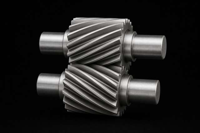
Helical pair — slanted teeth for smoother contact
Straight bevel gear
Shafts intersect. Pitch surfaces are cones, not cylinders.
Common case: Σ = 90° (right-angle drive).
Pitch cone angles (approx.):
tan γ₁ = (Z₁/Z₂)·sinΣ / (1 + (Z₁/Z₂)·cosΣ)
γ₂ = Σ − γ₁
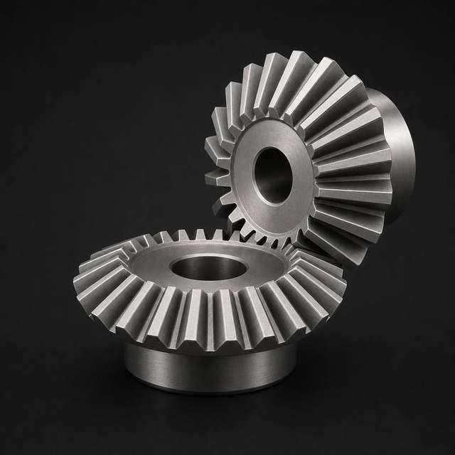
Straight bevel — intersecting shafts, conical pitch surfaces
Miter gear
A special bevel pair with equal teeth. Usually Σ = 90°.
Transfer ratio i = 1. Same speed, direction change only.
Use the calculator type “Miter” to lock that 1:1 case.
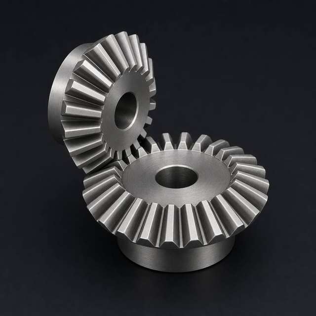
Miter gears — equal size, 90° turn, i = 1
Spiral bevel gear
Same cone layout as straight bevel, but teeth curve on the face.
Smoother, quieter mesh. Used in many vehicle differentials.
Cone angle math still starts from Σ, Z₁, and Z₂.
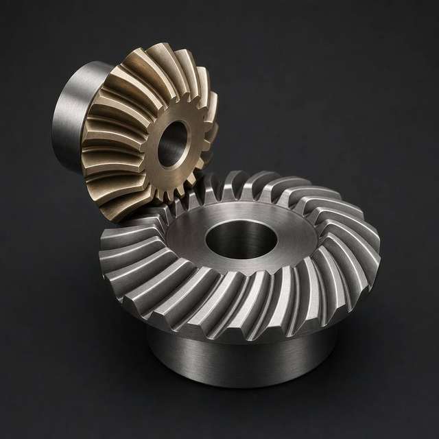
Spiral bevel — curved teeth on pitch cones
Hypoid gear
Like spiral bevel, but pinion axis is offset from the ring center.
Shafts do not intersect. Common in rear axles and differentials.
Offset lets the pinion sit lower and run quieter under load.
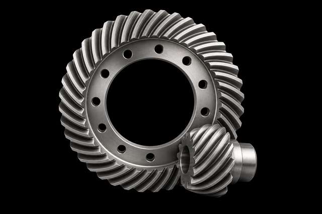
Hypoid — offset pinion, non-intersecting shafts
Screw gear (crossed helical)
Two helical gears on skew (non-intersecting, non-parallel) shafts.
Also called screw gears. Point contact; lower load than spur pairs.
Useful for light drives and odd shaft layouts.
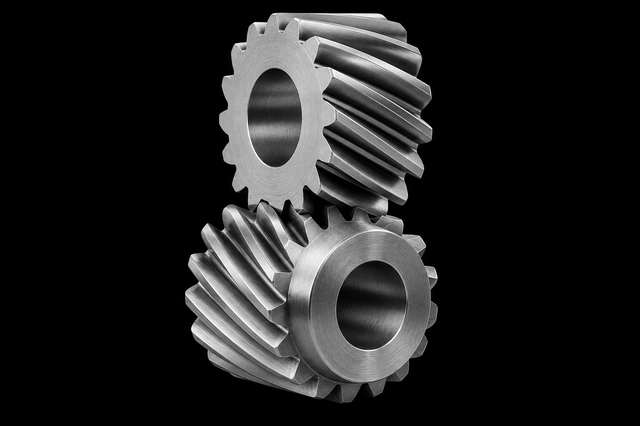
Screw gears — crossed helicals on skew axes
Worm
A screw-like driver on a shaft. Usually crossed at 90° to the wheel.
Approx. ratio: i ≈ Z_wheel / number of worm starts
Single-start worms self-lock more easily. Multi-start worms are faster.
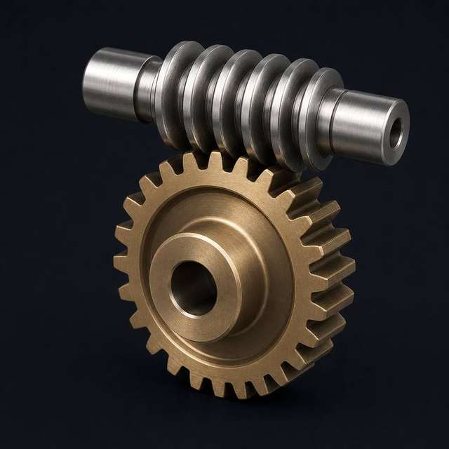
Worm drive — high ratio in one compact stage
Worm wheel
The mating gear for a worm. Often bronze for sliding wear.
Throat is concave so more teeth hug the worm thread.
Efficiency can be low. Heat and oil matter in real boxes.
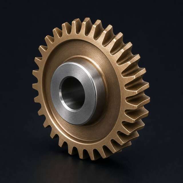
Worm wheel — throated gear for worm mesh
Rack & pinion
A rack is a gear with infinite radius — a straight tooth row.
Rotation becomes linear travel along the pitch line.
v = ω · (d/2) with d = m·Z for the pinion.
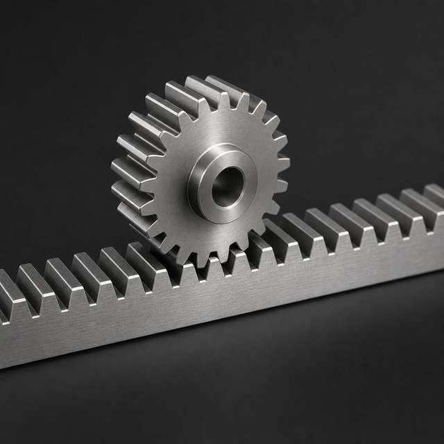
Rack & pinion — rotary to linear motion
Internal (annular) gear
Teeth cut inside a ring. Pinion sits inside.
Both rotate the same way. Center distance shrinks:
a = |d₂ − d₁| / 2
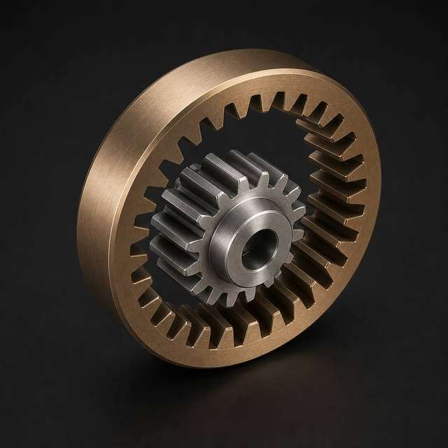
Internal gear — compact annular mesh
Planetary gear (epicyclic)
Sun in the center, planets on a carrier, ring gear outside.
Ratio depends on which member is fixed, input, or output.
Compact high ratio. Used in automatics, hubs, and reducers.
Simple case (ring fixed, sun in, carrier out): i ≈ 1 + Z_ring/Z_sun
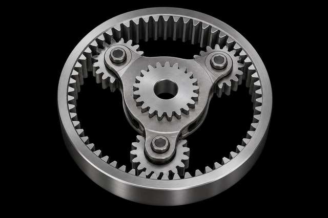
Planetary — sun, planets, and annulus ring
Gear coupling
Two hubs with external teeth inside a floating sleeve.
Passes torque while allowing small misalignment.
Not a speed reducer — treat i ≈ 1 in the calculator.
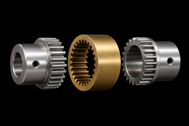
Gear coupling — torque across a flexible tooth sleeve
Pawl & ratchet
A toothed wheel plus a pawl that catches one way.
Used for winches, jacks, and one-way step feeds.
Motion is stepwise, not a continuous gear ratio.
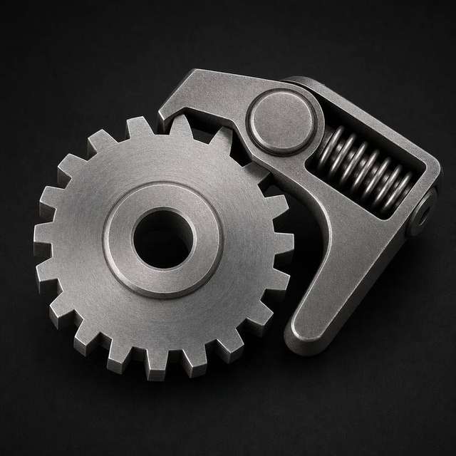
Pawl & ratchet — one-way incremental drive
Cam drive
A shaped disk or plate. A follower tracks the profile.
There is no fixed tooth ratio i. Stroke follows s(θ).
Use cams when you need a custom motion program.
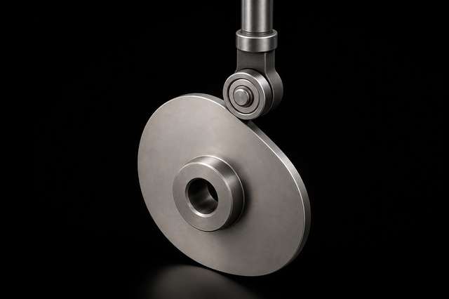
Cam & follower — programmed displacement vs angle
Herringbone gear (double helical)
Two opposite helixes meet in a V or chevron pattern on one blank.
Axial thrusts cancel. Quiet mesh without net end thrust.
Harder to cut than single helical. Ratio still follows Z₂/Z₁.
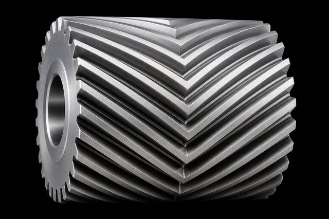
Herringbone — V-shaped teeth, opposing helixes
Transmission angles that matter
Angles by gear family
| Type | Key angle | What it sets |
|---|---|---|
| Spur / helical / herringbone | Pressure angle φ | Line of action tilt |
| Helical / screw | Helix angle β | Thrust & shaft skew |
| Bevel / miter / spiral / hypoid | Shaft Σ, cone γ, offset | How shafts meet |
| Planetary | Which member fixed | Which ratio path |
| Worm | Lead / lead angle | Advance per turn |
| Cam | Cam angle θ | Follower schedule |
| Ratchet | Tooth / pawl angle | Lock direction |
Parallel shafts → spur or helical. Intersecting → bevel family. Crossed → worm or screw.
Wrong family for the shaft layout is a layout error, not a module tweak.
Side-by-side cheat sheet
Quick compare
| Type | Shafts | Typical i | Watch-outs |
|---|---|---|---|
| Spur | Parallel | Low–medium | Noise at speed |
| Helical | Parallel | Low–medium | Axial thrust |
| Bevel / spiral | Intersecting | Low–medium | Cone setup |
| Hypoid | Offset / skew | Low–medium | Sliding, lube |
| Miter | Intersecting | 1:1 | Equal teeth |
| Screw | Skew | Low | Point contact |
| Worm | Crossed | High | Heat, friction |
| Rack | Rotary→linear | — | Backlash |
| Internal | Parallel | Medium | Same-way spin |
| Planetary | Coaxial train | Medium–high | Which member fixed |
| Coupling | Near-coaxial | ~1 | Misalignment only |
| Pawl / ratchet | One-way | Step | Impact loads |
| Cam | Custom motion | n/a | Profile wear |
| Herringbone | Parallel | Low–medium | Harder to cut |
Example setups
- Spur: Z₁=18, Z₂=36, m=2. Then d₁=36 mm, d₂=72 mm, a=54 mm, i=2.
- Slide Z₂ upward. Watch n₂ fall and τ₂ rise on the readouts.
- Switch to Bevel. Set Σ=90°, then 60°. Cone angles move.
- Miter: confirm i stays 1 with equal teeth.
- Worm: starts=1 vs 4 with same Z₂. Ratio changes a lot.
- Rack: ignore n₂. Read force-style output from torque.
- Hypoid: set Σ near 90°. Offset is the layout difference from spiral bevel.
- Planetary: treat Z₁ as sun, Z₂ as ring for a rough ring-fixed ratio.
- Herringbone: same ratio math as helical; thrust cancels.
- Coupling / pawl / cam: note that i is not a normal reducer.
Sources (.edu / .gov)
- UC San Diego MAE 3 — Gear ratios
- UNC Charlotte — Gear nomenclature
- Iowa State — Gear geometry notes (PDF)
- West Virginia University — Idealized spur gears (PDF)
- NIST Physical Measurement Laboratory
Teaching demo only. Not a substitute for AGMA design or a full machine-design course.
— Rajiv Nair
mechanism notes, rewritten for the bench
Comments
Write your view after login. Your comment appears only after the moderator approves it.
Or use email and password below.